
Objective
To learn how to use the Serial Monitor in the Arduino IDE for debugging, displaying data, and interacting with the ESP32 microcontroller. This experiment also introduces basic input/output interfacing using an LED and push button with serial feedback.
Introduction
The Serial Monitor is a built-in feature of the Arduino IDE that enables communication between a microcontroller and a computer. It is widely used for debugging, monitoring sensor data, and sending commands to the microcontroller. In this laboratory, you will explore how serial communication works and how it can be integrated with simple input/output components such as LEDs and push buttons.
Laboratory Equipment and Components
- ESP32 Development Board
- USB Cable
- Breadboard
- 1 × LED
- 1 × 220Ω Resistor
- 1 × Push Button
- Jumper Wires
- Computer with Arduino IDE
Theory
Serial communication transmits data bit by bit over a communication channel. In Arduino/ESP32 programming, serial communication is initialized using:
Serial.begin(9600);
Data can be sent using:
Serial.print("Text");
Serial.println("Text");
The Serial Monitor displays this data and can also send input back to the ESP32. This makes it a powerful debugging and interaction tool.
Circuit Diagram
The circuit consists of an LED connected to a GPIO pin and a push button connected to another GPIO pin with proper pull-down configuration.
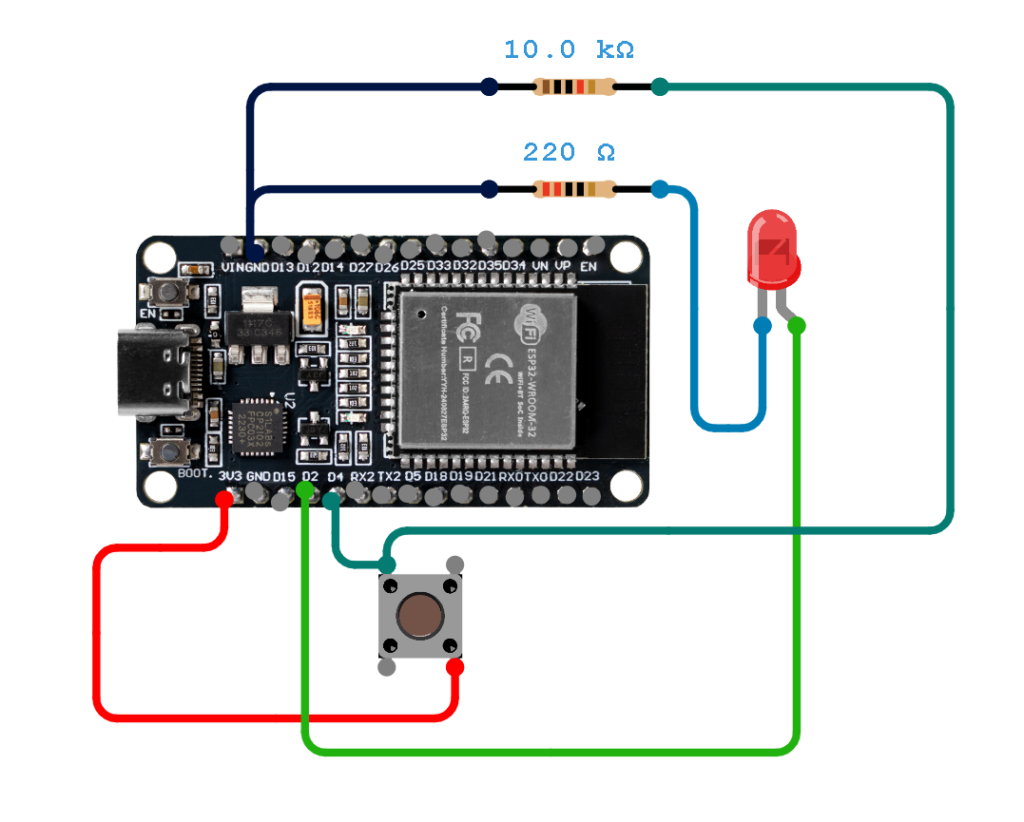
Connection Table
| Component | ESP32 Pin | Description |
|---|---|---|
| LED Anode (+) | GPIO 2 | Output pin to control LED |
| LED Cathode (-) | GND (via 220Ω resistor) | Current limiting connection |
| Push Button (One side) | GPIO 4 | Input pin for button reading |
| Push Button (Other side) | 3.3V | Provides HIGH signal when pressed |
| GPIO 4 (Pulldown) | GND | Use internal or external pull-down resistor |
| Push Button (Other side) | GND (via 10KΩ resistor) | Pull-down Resistor |
LED Circuit
The LED is connected to GPIO 2 with a current-limiting resistor. It will turn ON or OFF based on the push button state.
Push Button Circuit
The push button is connected to GPIO 4. When pressed, it sends a HIGH signal; otherwise, it remains LOW due to the pull-down configuration.
Experimental Procedure
Step 1: Assemble the Circuit
Build the circuit according to the connection table provided above.
Step 2: Connect the ESP32
Connect the ESP32 to your computer using a USB cable.
Step 3: Open Arduino IDE
Launch the Arduino IDE.
Step 4: Select the Board
Go to Tools → Board → ESP32 Dev Module and select the correct COM port.
Step 5: Write the Program
const int ledPin = 2;
const int buttonPin = 4;

void setup() {
  pinMode(ledPin, OUTPUT);
  pinMode(buttonPin, INPUT);
  Serial.begin(9600);
}

void loop() {
  int buttonState = digitalRead(buttonPin);

  if (buttonState == HIGH) {
    digitalWrite(ledPin, HIGH);
    Serial.println("Button Pressed - LED ON");
  } else {
    digitalWrite(ledPin, LOW);
    Serial.println("Button Released - LED OFF");
  }

  delay(500);
}
Step 6: Upload the Program
Upload the code to the ESP32 and wait for completion.
Expected Output
Open the Serial Monitor and set the baud rate to 9600. You should observe:
To open the serial monitor just press the key combination: Ctrl + Shitf + M
- When the button is pressed: “Button Pressed – LED ON”
- When the button is released: “Button Released – LED OFF”
The LED should turn ON and OFF accordingly.
Discussion
This experiment demonstrates how serial communication can be integrated with hardware input and output. The Serial Monitor provides real-time feedback, making it easier to debug and understand system behavior. By combining button input and LED output, the system becomes interactive and more practical.
Such setups are commonly used in embedded systems for monitoring sensor values, controlling devices, and testing logic before deploying full applications.
Conclusion
In this lab, you successfully used the Serial Monitor to observe and control an ESP32-based system. You learned how to interface input and output devices and how to use serial communication for debugging and interaction. These skills are essential for developing more complex embedded systems.
Guide Questions
- What is the role of the Serial Monitor in this experiment?
- Why is a resistor needed in the LED circuit?
- What would happen if the baud rate is mismatched?
- How does the push button affect the LED behavior?
- How can serial communication be used for debugging more complex systems?
Arduino Random Number Primer
The random() function in Arduino is used to generate pseudo-random numbers, which are useful for simulating sensor readings, games, or unpredictable behavior in your projects.
1. Basic Usage
Use random(min, max) to generate a number between min (inclusive) and max (exclusive).
void setup() {
  Serial.begin(9600);
}

void loop() {
  long randNumber = random(0, 101); // 0 to 100
  Serial.println(randNumber);
  delay(1000); // Wait 1 second
}
Explanation:
random(0, 101)→ generates integers from 0 to 100.Serial.println()prints the number to the Serial Monitor.delay(1000)adds a 1-second pause between numbers.
2. Single Parameter Version
If you provide only one parameter, it generates numbers from 0 up to (but not including) that value:
long randNumber = random(50); // 0 to 49
3. Improving Randomness
Arduino’s random numbers are pseudo-random and repeat the same sequence unless you change the seed:
void setup() {
  Serial.begin(9600);
  randomSeed(analogRead(A0)); // Use an unconnected analog pin for variability
}

void loop() {
  long randNumber = random(0, 101);
  Serial.println(randNumber);
  delay(1000);
}Tip: randomSeed() should be called once in setup() to generate a different sequence each time the board restarts.
4. Practical Example: Simulated Sensor
Use random() to simulate sensor values and warnings:
void setup() {
  Serial.begin(9600);
  randomSeed(analogRead(A0));
}

void loop() {
  int sensorValue = random(0, 101);
  Serial.print("Sensor reading: ");
  Serial.println(sensorValue);

  if (sensorValue > 80) {
    Serial.println("Warning: High value!");
  }

  delay(1000);
}
This example demonstrates:
- Generating random numbers
- Using
ifstatements - Printing output to the Serial Monitor
5. Summary
random(min, max)→ generates integers frommintomax-1random(max)→ generates integers from 0 tomax-1randomSeed(seed)→ ensures a different sequence each time- Use
Serial.print()andSerial.println()to display numbers
After Guide Assessment: Arduino IDE Serial Monitor (Hands-On)
Test your understanding of the Arduino Serial Monitor by completing the following exercises. Each task requires using Serial.print(), Serial.println(), Serial.read(), and/or Serial.begin().
Exercise 1: Basic Output
Write a sketch that:
- Initializes serial communication at 9600 baud.
- Prints your name to the Serial Monitor once every 2 seconds.
Challenge: Use Serial.print() and Serial.println() together to print your first and last name on the same line, then move to a new line for the next output.
Exercise 2: Counting Numbers
Write a sketch that:
- Prints numbers from 1 to 20 in the Serial Monitor, one per line.
- Waits 500 milliseconds between each number.
Challenge: Use a for loop and Serial.print() to print numbers on the same line, separated by commas, and then use Serial.println() after the loop to go to the next line.
Exercise 3: User Input
Write a sketch that:
- Prompts the user in the Serial Monitor to enter a number.
- Reads the number using
Serial.read()orSerial.parseInt(). - Prints a message like “You entered: [number]” back to the Serial Monitor.
Challenge: Handle invalid inputs (like letters) gracefully.
Exercise 4: Interactive Sensor Simulation
Simulate a sensor by writing a sketch that:
- Generates a random number between 0 and 100 every second.
- Prints “Sensor value: [number]” to the Serial Monitor.
- If the value is above 80, print “Warning: High value!”
Challenge: Try using both if statements and serial output formatting.
Exercise 5: Debugging Practice
The following code has errors that prevent it from printing correctly to the Serial Monitor:
void setup() {
  Serial.begin(9600);
}

void loop() {
  Serial.print("Count: ");
  for(int i=0; i<=5; i++);
    Serial.println(i);
  delay(1000);
}Tasks:
- Identify and fix the errors so that the Serial Monitor correctly prints numbers 0 to 5 each second.
- Explain why the original code did not work as intended.


1.
The Serial Monitor acts as the bridge between your computer and the ESP32, enabling you to send real-time commands and view the system’s output for monitoring and control.
2.A resistor is essential to limit current flow; without it, the LED would draw excessive power, likely damaging the component or the ESP32’s GPIO pin.
3.A baud rate mismatch causes the timing of data bits to desynchronize, resulting in the Serial Monitor displaying unreadable symbols or “garbage” text instead of your data
4.The push button serves as a digital trigger; when pressed, the ESP32 detects the signal change and executes a programmed instruction to toggle or modify the LED’s state.
5.Serial communication facilitates debugging by allowing you to print internal variable values and status updates, making it easier to track logic errors in sophisticated codebases.
1. What is the role of the Serial Monitor in this experiment?
The Serial Monitor is used to display data and send commands between the computer and the ESP32. It helps you see what the program is doing (like button states or messages) and is useful for testing and debugging.
2. Why is a resistor needed in the LED circuit?
A resistor is needed to limit the current flowing through the LED. Without it, too much current can pass and damage or burn out the LED.
3. What would happen if the baud rate is mismatched?
If the baud rate is not the same in both the code and Serial Monitor, the output will appear as garbled or unreadable characters, and communication won’t work properly.
4. How does the push button affect the LED behavior?
The push button acts as an input switch. When pressed, it sends a signal to the ESP32, which then turns the LED ON or OFF depending on the program logic.
5. How can serial communication be used for debugging more complex systems?
Serial communication helps by printing variable values, system status, and error messages. This allows you to track what’s happening inside the program and quickly identify problems in more complex systems.
Guzman
Duque
Guillermo
Morales
Mendoza
makaBUGong Agrikultura
1. What is the role of the Serial Monitor in this experiment?
It is to manipulate the amount of baud rate of the program.
2. Why is a resistor needed in the LED circuit?
A resistor is an essential need in LED circuit because it keeps the current below the LED’s maximum rated limit. It also stabilizes the current when the LED starts to heat up to prevent thermal runaway.
3. What would happen if the baud rate is mismatched?
Proper configuration of baud rate ensures reliable that is error-free, while mismatched rates lead to data loss.
4. How does the push button affect the LED behaviour
The push button acts as a switch in the circuit. When the push button is pressed the LED is ON. While if released the LED is OFF.
5. How can serial communication be used for debugging more complex systems?
Serial communication helps in debugging complex systems because it lets the coder see data as the program runs, send messages from different parts of the code, and watch what the system is doing step by step. Since data is sent one at a time, it is easier to find errors, check values, and know where the problem is.
CORNpilers
1. The Serial Monitor serves as a communication interface that displays data sent from the ESP32 to a computer. It allows for the observation of real-time program behavior, such as verifying whether a button press is being registered, without relying solely on physical indicators like an LED.
2. A resistor is included to limit the amount of electrical current flowing through the LED. Because LEDs have very low resistance, they can easily draw too much power from the ESP32, which would result in the LED burning out or the microcontroller’s GPIO pin being damaged. The resistor keeps the current at a safe level.
3. A baud rate mismatch occurs when the transmission speed of the ESP32 does not match the setting on the Serial Monitor. This causes the data bits to be interpreted at the wrong timing, leading to the display of “garbage” characters, symbols, or unreadable text instead of the actual intended messages.
4. The push button acts as a digital input that controls the flow of electricity to a specific GPIO pin. When the button is pressed, the pin reads a HIGH state, which the program uses as a trigger to turn the LED on. When the button is released, the pin reads a LOW state, prompting the program to turn the LED off.
5. Serial communication is a tool for identifying errors in logic or hardware connections. By printing variable values, sensor data, or status messages to the monitor, it becomes possible to track exactly where a program is failing. This is especially useful in complex systems where multiple components are working simultaneously and physical symptoms are not enough to diagnose a problem.
1.The Serial Monitor serves as a communication interface between the Arduino and your computer. It allows you to:
a). View real-time data printed by the Arduino (e.g., button states, sensor readings).
b).Send commands from your computer to the Arduino to control behavior (like toggling the LED).
c).Debug the program by displaying messages that confirm what the code is doing step by step. Essentially, it acts as a text-based window into the Arduino’s runtime behavior.
2. A resistor is needed to limit the current flowing through the LED. LEDs have very low internal resistance, so without a current-limiting resistor, too much current would flow through them, which would either burn out the LED or damage the Arduino’s output pin. The resistor ensures the current stays within a safe operating range (typically around 10–20 mA for standard LEDs).
3. If the baud rate set in the Arduino sketch (e.g., Serial.begin(9600)) does not match the baud rate selected in the Serial Monitor, the communication would be out of sync. As a result:
a). Text output would appear as garbled, random, or unreadable characters.
b). Commands sent from the Serial Monitor would not be interpreted correctly by the Arduino.
The experiment would fail to work as intended since neither side can properly decode the other’s data. Always make sure both sides use the same baud rate to ensure reliable serial communication.
4. The push button acts as the input trigger for the LED output. When the button is pressed, GPIO 4 reads HIGH, which causes the program to set GPIO 2 HIGH, turning the LED on. When the button is released, GPIO 4 returns to LOW due to the pull-down resistor configuration, and the program turns the LED off. In short, the button directly controls the LED state through the program logic.
5. In complex systems, serial communication allows developers to print variable values, sensor readings, and system states at key points in the code, helping to identify unexpected behavior. For example, you can verify each sensor’s output in a multi-sensor system or log a decision-making algorithm’s steps for logic verification. It also enables sending commands from the computer to the microcontroller during runtime, allowing for testing different inputs without re-uploading code. Essentially, it replaces the need for a hardware debugger in many embedded development scenarios.
CORN.HUB ANSWERS
1. The Serial Monitor is used to display messages and data from the microcontroller to the computer. It helps monitor the status of the circuit, such as when the button is pressed or when the LED turns on and off.
2. A resistor is needed to control the flow of electricity going to the LED. Without it, too much current can pass through and may damage or burn out the LED.
3. If the baud rate of the Arduino and the Serial Monitor do not match, the displayed text will appear as unreadable or random symbols. This happens because both sides are not communicating at the same speed.
4. The push button acts as a switch that controls the LED. When the button is pressed, it sends a signal to the microcontroller, which can turn the LED on or off depending on the program.
5. Serial communication helps by showing real-time values and system responses while the program is running. It makes it easier to find errors, check sensor readings, and confirm if the circuit is working correctly.
Cornpilers [Cabutaje, Callangan, Malazza, Miranda, Tabugay]
1. The Serial Monitor serves as a communication interface that displays data sent from the ESP32 to a computer. It allows for the observation of real-time program behavior, such as verifying whether a button press is being registered, without relying solely on physical indicators like an LED.
2. A resistor is included to limit the amount of electrical current flowing through the LED. Because LEDs have very low resistance, they can easily draw too much power from the ESP32, which would result in the LED burning out or the microcontroller’s GPIO pin being damaged. The resistor keeps the current at a safe level.
3. A baud rate mismatch occurs when the transmission speed of the ESP32 does not match the setting on the Serial Monitor. This causes the data bits to be interpreted at the wrong timing, leading to the display of “garbage” characters, symbols, or unreadable text instead of the actual intended messages.
4. The push button acts as a digital input that controls the flow of electricity to a specific GPIO pin. When the button is pressed, the pin reads a HIGH state, which the program uses as a trigger to turn the LED on. When the button is released, the pin reads a LOW state, prompting the program to turn the LED off.
5. Serial communication is a tool for identifying errors in logic or hardware connections. By printing variable values, sensor data, or status messages to the monitor, it becomes possible to track exactly where a program is failing. This is especially useful in complex systems where multiple components are working simultaneously and physical symptoms are not enough to diagnose a problem.
1. The Serial Monitor acts as the communication bridge between the ESP32 and the user. It provides real-time feedback by displaying messages, sensor readings, and system states, which makes it easier to observe how the program responds to inputs like button presses. In this experiment, it allowed you to confirm that the LED and button logic were working correctly, while also serving as a debugging tool to trace errors or unexpected behavior before deploying more complex systems.
2. A resistor is essential because it limits the current flowing through the LED. Without it, the LED could draw excessive current directly from the ESP32 pin, potentially damaging both the LED and the microcontroller. By controlling the current, the resistor ensures safe operation, prolongs the LED’s lifespan, and stabilizes brightness output, which is critical in reliable embedded system design.
3. If the baud rate set in the code does not match the baud rate configured in the Serial Monitor, the communication becomes garbled. Instead of readable text or sensor values, you would see random characters or corrupted data. This mismatch prevents proper debugging and monitoring, making it difficult to verify whether the system is functioning as intended. Correct baud rate alignment ensures smooth, accurate data transfer between the ESP32 and the computer.
4. The push button serves as a digital input that directly influences the LED’s state. When pressed, it changes the logic level read by the ESP32, which in turn triggers the LED to turn on or off depending on the programmed condition. This interaction demonstrates how input devices can control output devices, making the system interactive and practical. It also reflects the fundamental principle of embedded systems: combining inputs and outputs to create responsive applications.
5. In larger embedded projects, serial communication becomes a vital diagnostic tool. Developers can print sensor readings, variable states, or error messages to the Serial Monitor to trace issues step by step. For example, when integrating multiple sensors or actuators, serial logs help identify which part of the system is failing or behaving unexpectedly. This makes debugging more systematic and efficient, reducing development time and ensuring that complex systems remain reliable